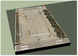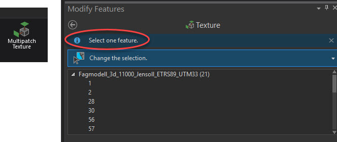


Points with 3D symbols, extruded lines, and polygons will be exported as multipatch features. 3D model marker symbols whose size is denoted in real-world linear units such as feet, inches, meters, or centimeters. They already have Z information in their geometry. Extruded points will be exported as 3D lines. Feature layers with symbology that has the following properties will be exported to a multipatch: Extrusion or base height settings. Open the scene containing the multipatch or 3D object feature you want to edit.

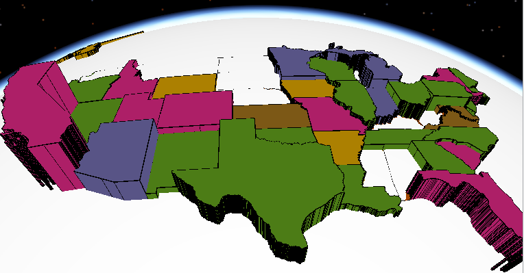
3D features can be displayed without the need to draping them over a surface like DEM. Adding and extruding text in Fusion 360 can be simple but requires some. Extrude the 2D features, using the attribute height field, to display them in 3D. For many 3D spatial Analysis, you need 3D features or Multipatch features.ģD features are features with 3D geometry. It is just a 3D visualization of your 2D data. Having an extruded building, does not make your features with 3D geometry. It means that you extruded a 2D polygon based on a ‘Z’ attribute you extracted from LiDAR Data or DSM or any other sources. GIS professionals with the 3D Analyst extension can also use their SketchUp models as 3d Marker Symbols or export them as Multipatch features for further. Note: What you have created in Lesson 5 as a 3D building, is an extrusion from attribute. Ive inserted the required parameters which are the 3d layer ( not feature class) as input, an output multipatch feature class and a grouping definition by the OBJECTID field. Make sure the following layers are checked in the 3D Layers Content Pane: Up_Roof_Segments, Building_Footprints., and Topography. The screenshots below are the subsequent service layers in a WAB (dev edition) application. The extruded layer was then converted to a multipatch via the Layer 3D to Feature Class tool. In the Projects Folder (C:\Users\YOURUSER\Documents\ArcGIS\Projects\ UniversityParkCampus), Save Project as UniversityParkCampus_Lesson6_Shadow. The multipatch was created by extruding the features to a depth from surface field in ArcPro (relative to ground).A final discussion summarises on advantages and disadvantages of the used approach and outlines directions for further research. This paper presents the used systems architecture and developed prototype. This paper presents an approach for utility management, according to which the pipelines and cables are still maintained as lines but while visualising in 3D, the lines are substituted with cylinders created on the fly. However, substituting simple lines with parametric shapes in the database is time consuming, expensive and economically not justified. We will apply the extrusion by adding it to the. In most of the cases, the best solution is to replace the lines with tiny cylinders or other 3D shapes. In the drop down menu Apply Extrusion by: choose the option adding it to each features minimum height. Browse to the location of the 3D model on disk you want to use. Click the 3D Editor drop-down menu and click Replace With Model. Hold the Shift key to select multiple features. This exercise walks the reader through the process of creating and adding texture to a 3D multipatch feature. ArcGIS 10 introduces a host of new 3D data management and analysis capabilities that enhance 3D analysis. Generally, visualization of lines in 3D is quite challenging. Select the multipatch feature or features that you want to edit. The multipatch, Esri's native 3D feature type, is a key element whether working in ArcGlobe or ArcScene. Therefore the interest in 3D visualization is rapidly increasing.

Such visualization might be misunderstood by both field workers (maintaining the utilities) and specialists. Since the position is visualized on 2D maps, it is rather difficult to distinguish between cables and pipelines with the same x,y coordinates. I’m excited to announce that were giving away TWO VORON V0. The systems used for maintenance of utilities are typically two-dimensional, allowing for creating vertical profiles in limited key places. Utility networks (pipelines and cables) are usually modelled by lines and nodes.


 0 kommentar(er)
